An easy to build UHF array is illustrated in the above picture.
As in the VHF array, a very good capacitive coupling to the roof metal is essential.
Due to the shorter UHF wavelength, another approach is feasable:
Simply take a sheet of aluminum as a ground surface.
Taped to the car roof it provides very good capacitive coupling, so the car roof extends the ground surface.
Below some pictures to illustrate the process.
This is the schematic of the antenna array.
For the RDF41 stick to this schematic.
Note that for the conventional V2,3 doppler the 1k resistors may be changed into 470nH inductors.
Take an aluminum sheet of 50x50cm. Thickness 1 up to 2mm.
1mm thick is sturdy enough, it flexes enough to adapt to the curvature of most car roofs.
A 2mm thick sheet is a lot stiffer, but can still be pre-bent to fit the curvature nicely.
Note that this undersized ground plate should be taped flat to the car roof, because only this way the roof will extend the ground surface.
Mark the center of the sheet, and draw a cross to the corners.
At 12 cm distance from the center, draw markings for the antenna positions.
(For the Amplitude Array this distance should be 15.5cm.)
The antenna position in the bottom left corner is already drilled in this picture.
Note that the antenna center holes are 10mm, to avoid electrical contact between antenna screw and ground plate. The fastening holes are 3mm. The fastening screws will have to provide electric contact to the ground plate.
On the back side the 3mm holes are countersunk to accept the countersunk screwheads.
The screwheads should not protrude because they will damage your car paint!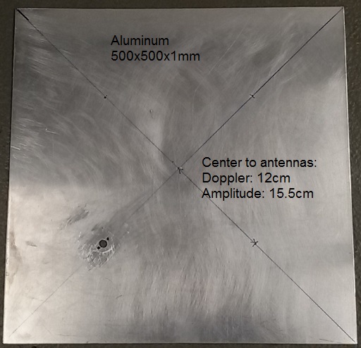
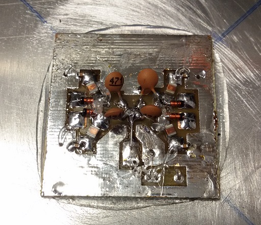
Now, the small antenna PCB’s can be screwed in place.
Apply a good sealer between PCB and aluminum to prevent water to creep in.
I countersunk the bottom side of the center hole of the PCB to make sure that the screwheads have good clearance to the below car roof.
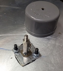
With a spacer bolt of the right length the total length matches the inside height of the cups I use as enclosure.
The actual antenna goes on top of all that.
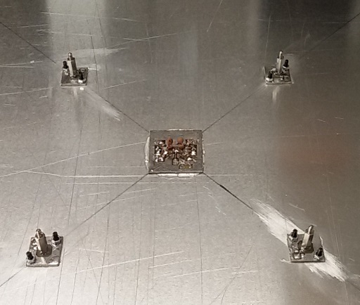
After mounting these antenna PCB’s and spacer bolts, I sealed the antenna base holes on the bottom side using silicone sealer.
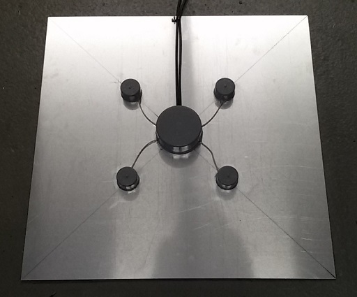
Then, the center PCB (combiner) is glued in place using silicone sealer.
Here the antenna PCB’s are added.
All wired up.
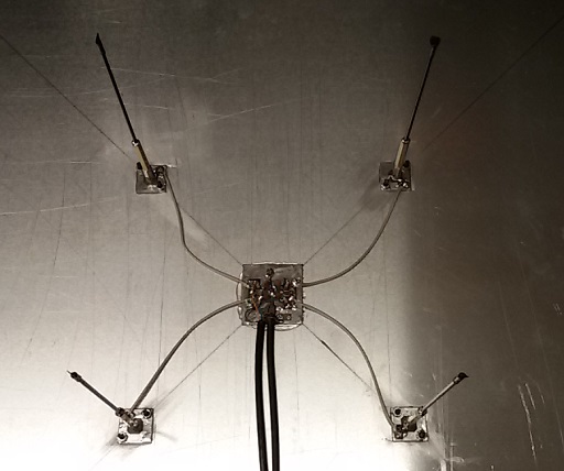
All caps glued in place.
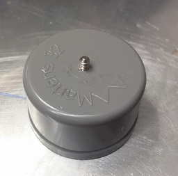
The actual screw-on antenna and reflectors are made using identical metal spacers with a length of steel wire drilled and soldered in its top.
Overall length including all spacers should be 17cm for all 4 antennas, top to ground plate.
I covered the steel wire in heat shrink tubing, in that case you may shorten the elements by 5%.
The picture on the left shows 3 stadia of a reflector:
Bottom: Standard brass M3 spacer .
Middle: Threaded stub removed and 2mm hole drilled into the center, about 4mm deep.
Top: Steel antenna wire soldered in and covered in heat shrink tubing.

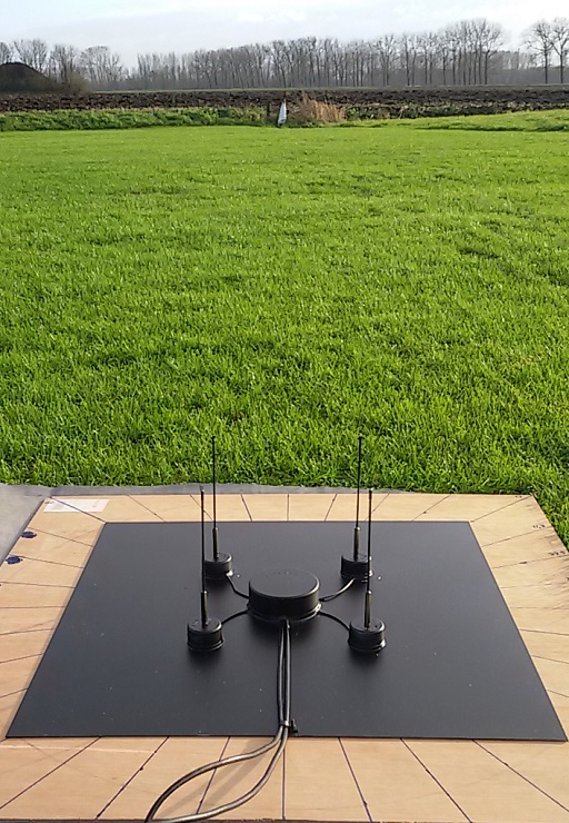
The finished Array ready for a paint job.
The finished Array during a field test @433,2MHz.
Averaged error: 2,2 degrees.
Peak error: 4,5 degrees.